1.Features:
① Vertical core-through, multi-point fixation;
② Used for single or multiple busbar crossing, especially vertical busbar crossing;
③ The output terminal is a screw fastened crimping type standard terminal, which is convenient for wiring at the engineering site;
④ Box structure, closed plastic case, beautiful appearance.
2.Ambient Conditions:
① Ambient temperature: -30℃~+70℃;
② Relative humidity: ≤90% at 40℃;
③ Atmospheric pressure: 860~1060mbar(about 650~800mmHg).
3.Operating Frequency Range: 50 Hz or 60 Hz
4.Insulation Thermal Class:Class E ( 120℃).
5.Safety Features:
① Insulation resistance: >1000MΩ in normal condition;
② Insulation withstand voltages: 3000V 50Hz/1min;
③ Fire retardancy: In conformity with UL94-V0.
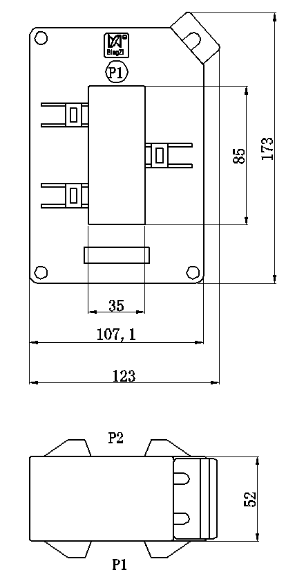
6.Outline Drawing, Installation Dimensionand Coil Diagram: (tolerance±1mm)
① Outline drawing and installation dimensions are shown in Figure 1:
② The coil diagram is shown in Figure 2:


● Note: Each product is supplied with six suction cups and six M5 fixing busbar screws.
7. Typical Application and Performance Parameters:
See the table below for performance parameters when applied as shown in Figure 3.

Model | Rated Input Current | Rated Output Current | Rated Sampling Resistance RL | Rated Sampling Voltage | Non-linearity |
TAH8535-1 | 400A | 5A | 0.267Ω | 1.33V | ≤0.5% |
TAH8535-2 | 500A | 5A | 0.333Ω | 1.66V | ≤0.5% |
TAH8535-3 | 600A | 5A | 0.4Ω | 2V | ≤0.5% |
TAH8535-4 | 750A | 5A | 0.5Ω | 2.5V | ≤0.5% |
TAH8535-5 | 1000A | 5A | 0.667Ω | 3.33V | ≤0.5% |
TAH8535-6 | 1200A | 5A | 0.8Ω | 4V | ≤0.5% |
TAH8535-7 | 1500A | 5A | 1Ω | 5V | ≤0.5% |
TAH8535-8 | 2000A | 5A | 1.33Ω | 6.66V | ≤0.5% |
TAH8535-9 | 2500A | 5A | 1.66Ω | 8.33V | ≤0.5% |
TAH8535-10 | 3000A | 5A | 2Ω | 10V | ≤0.5% |
● Note:
a. In practical applications, the sampling resistance should be less than or equal to the rated value given in the above table, which will improve the nonlinearity and phase shift;
b. If the conversion ratio required by the user is different from the above, it can be customized according to the user's requirements.
8.Attention:
① Connect the primary of the current transformer in series with the measured current loop, and operate the secondary in near short circuit mode.
② Do not allow the secondary of the current transformer to be open circuit and do not install any fuse.

WeChat Official Account