 Beijing TransFar Electronics Group Co., Ltd

1.Features:
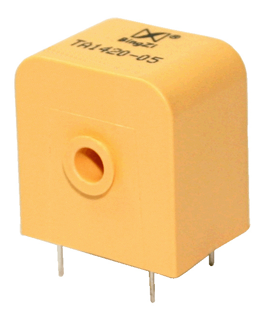
① This product is designed to be directly welded onto a PCB.
② It is fully encapsulated, providing strong mechanical and environmental endurance, strong dielectric strength, and a beautiful appearance.
③ With high accuracy, a wide sampling range, and flexibility in usage, it is a reliable and versatile component for various applications.
2.Ambient Conditions:
① Ambient temperature: -55℃~+85℃;
② Relative humidity: ≤90% at 40℃;
③ Atmospheric pressure: 860~1060mbar(about 650~800mmHg).
3.Operating Frequency Range: 20Hz~1kHz
4.Insulation Thermal Class:Class F (155℃)
5.Safety Features:
① Dielectric resistance: >1000MΩ in normal condition;
② Insulation withstand voltages: 6000V 50Hz/1min;
③ Fire retardancy: In conformity with UL94-V0.
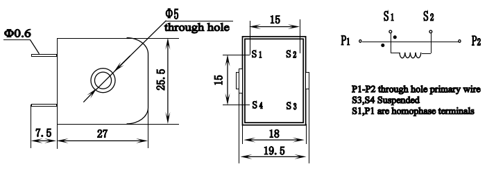
6.Outline Drawing, Installation Dimension and Coil Diagram: ( tolerance ± 0.5mm )

7.Typical Application and Technical Parameters:
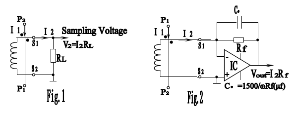
①The parameters are listed in Table 1 while the sampling voltage is obtained directly by using a resistor (as shown in Fig.1 below).
②The parameters are listed in Table 2 while the sampling voltage is obtained by using an IC (as shown in Fig.2 below).

Table 1:
Model | Rated Input Current | Rated Output Current | Rated Sampling Resistor RL | Rated Sampling Voltage | Phase Shift | Non Linearity | Linear Range | Withstand Voltage |
TA1420-01 | 5A | 5mA | 200Ω | 1V | ≤30’ | ≤0.2% | ≥2 times of the rated value | ≥6KV |
TA1420-01M | 5A | 5mA | 250Ω | 1.25V | ≤37’ | ≤0.25% | ||
TA1420-02 | 10A | 5mA | 400Ω | 2V | ≤20’ | ≤0.2% | ||
TA1420-02M | 10A | 5mA | 500Ω | 2.5V | ≤25’ | ≤0.25% | ||
TA1420-03 | 15A | 5mA | 600Ω | 3V | ≤15’ | ≤0.2% | ≥1.5 times of the rated value | |
TA1420-03M | 15A | 5mA | 750Ω | 3.75V | ≤19’ | ≤0.25% | ||
TA1420-04 | 20A | 5mA | 800Ω | 4V | ≤12’ | ≤0.2% | ||
TA1420-04M | 20A | 5mA | 1000Ω | 5V | ≤15’ | ≤0.25% | ||
TA1420-05 | 25A | 5mA | 1000Ω | 5V | ≤10’ | ≤0.2% | ≥1.2 times of the rated value | |
TA1420-05M | 25A | 5mA | 1250Ω | 6.25V | ≤12.5’ | ≤0.25% | ||
TA1420-06 | 30A | 5mA | 1200Ω | 6V | ≤9’ | ≤0.2% | ||
TA1420-06M | 30A | 5mA | 1500Ω | 7.5V | ≤11’ | ≤0.5% |
Table 2:
Model | Rated Input Current | Rated Output Current | Rated Sampling Voltage | Phase Shift | Non Linearity | Linear Range | Withstand Voltage |
TA1420-01 | 5A | 5mA | ≤1/2 IC’s power supply | ≤5’ | ≤0.1% | ≥2 times of the rated value | ≥6KV |
TA1420-01M | 5A | 5mA | |||||
TA1420-02 | 10A | 5mA | |||||
TA1420-02M | 10A | 5mA | |||||
TA1420-03 | 15A | 5mA | |||||
TA1420-03M | 15A | 5mA | |||||
TA1420-04 | 20A | 5mA | |||||
TA1420-04M | 20A | 5mA | |||||
TA1420-05 | 25A | 5mA | |||||
TA1420-05M | 25A | 5mA | |||||
TA1420-06 | 30A | 5mA | |||||
TA1420-06M | 30A | 5mA |
8.Attention:
① Connect the primary winding of the current transformer in series with the measured current loop, and operate the secondary winding in near short-circuit mode.
② Do not allow the secondary winding of the current transformer to be open-circuited and do not install any fuse in the secondary circuit.